BIO-REACTORS
INTRODUCTION
Bioreactors for treatment of metal bearing wastewater have typically the same configuration as that of traditional catalytic chemical reactors used in petrochemical industry or the bioreactors used in biotechnology applications, or the activated sludge reactors employed in the treatment of municipal waste water treatment plants (WWTP). Microorganisms immobilized mainly in the form of biofilm on the surface of a carrier material, act as live bio-catalysts with the advantage of the self-regenerating feature. The sequestering of metal ions from a liquid phase usually differs from the utilization and removal of the organic content (BOD/COD) from wastewater. The main mechanisms involved in the sequestering of metal ions have been described in the learning object entitled "Metal Imobilization Process" and are these responsible for the interaction of microbial biomass with metals, in order to reduce the mobility of the last. These mechanisms are hosted in the environment of a reactor as described in the following sections.
Single Phase Reactors - Reactor Types and Operating Characteristics
Single phase reactors:
All reactors, either chemical reactors or bioreactors, have in common selected characteristics of four basic reactor types:
- The well-stirred batch reactor,
- The semi-batch reactor or fed batch reactor,
- The continuous-flow stirred-tank reactor (CSTR), and
- The tubular reactor or plug flow reactor.
- Any reactor may be represented by or modeled after one or a combination of these types.
Well-stirred batch reactors
The stirred tank batch reactor is still the most widely used reactor type both in the laboratory and industry. A batch reactor is one in which a feed material is treated as a whole for a fixed period of time. Batch reactors may be preferred for small-scale production of high priced products, particularly if many sequential operations are employed to obtain high product yields. Batch reactors also may be justified when multiple, low volume products are produced in the same equipment or when continuous flow is difficult, as it is with highly viscous or sticky solids-laden liquids. Because residence time can be more uniform in batch reactors, better yields and higher selectivity may be obtained than with continuous reactors.
Batch reactors often are used because of their suitability and convenient use mainly in laboratory experimentation. Industrial practice generally favors processing continuously rather than in single batches, because overall investment and operating costs usually are less. Data obtained in batch reactors can be well defined and used to predict performance of larger scale, continuous-flow reactors. Almost all batch reactors are well stirred; thus, ideally, compositions are uniform throughout and residence times of all contained reactants are constant.
Although various types of agitators can be used with different shear patterns imposed, the major problem with stirred tank reactors is abrasion of the matrix particles. This abrasion is not only due to the mixer blades or generated shear but also to some extent to the air injection. By packing the gel beads, porous particles or other packing in a draft tube, this abrasion can be limited. In fact a submerged packed bed with external recycle results and the mixer is acting as a pump, and the rest of the vessel as a re-circulation reservoir. Impellers such as helical ribbon, screw or anchor are preferred over turbines or propellers for their more gentle stirring. Smaller particles are less subject to shear and these also have fewer chances of diffusion limit of the conversion rates. Their separation at the exit of the reactor might, however, be more problematic.
Batch reactors are rarely used as standalone reactor configuration in municipal or industrial waste water treatment units, except of certain cases such as pH adjustment of a stream (i.e. by addition of alkali to neutralize a batch) or for chemical precipitation of dissolved metals (i.e. removal of metal ions by alkaline precipitation). Figure 1, present typical proportions of a well stirred batch reactor and Figure 2 a typical picture.
 Figure 1
 - Typical proportions of a well stirred batch reactor.
Figure 2 - A Typical Batch Reactor.
Semi batch reactors or fed batch reactors
The semi batch reactor is similar to the batch reactor but has the additional feature of continuous addition or removal of one or more components / streams. In addition to better yields and selectivity, gradual addition or removal assists in controlling temperature particularly when the net reaction is highly exothermic. Thus, use of a semi batch reactor intrinsically permits more stable and safer operation than in a batch operation. Fed batch reactors are rarely used in waste water treatment units.
Continuous-flow stirred-tank reactor (CSTR)
In a continuous-flow stirred-tank reactor (CSTR), reactants and products are continuously added and withdrawn. In practice, mechanical or hydraulic agitation is required to achieve uniform composition and temperature, a choice strongly influenced by process considerations. The CSTR is the idealized opposite of the well-stirred batch and tubular plug-flow reactors. Analysis of selected combinations of these reactor types can be useful in quantitatively evaluating more complex gas-, liquid-, and solid-flow behaviors.
 Figure 3
. Continuous stirred tank reactors, (a) With agitator and internal heat transfer surface, (b) With pump around mixing and external heat transfer surface, (adopted by ref. 5).
Because the compositions of mixtures leaving a CSTR are those within the reactor, the reaction driving forces, usually the reactant concentrations, are necessarily low. Therefore, except for reaction orders zero- and negative, a CSTR requires the largest volume of the reactor types to obtain desired conversions. However, the low driving force makes possible better control of rapid exothermic and endothermic reactions. When high conversions of reactants are needed, several CSTRs in series can be used. Equally good results can be obtained by dividing a single vessel into compartments while minimizing back-mixing and short-circuiting. The larger the number of CSTR stages, the closer the performance approaches that of a tubular plug-flow reactor.
Continuous-flow stirred-tank reactors in series are simpler and easier to design for isothermal operation than are tubular reactors. Reactions with narrow operating temperature ranges or those requiring close control of reactant concentrations for optimum selectivity benefit from series arrangements. If severe heat-transfer requirements are imposed, heating or cooling zones can be incorporated within or external to the CSTR. For example, impellers or centrally mounted draft tubes circulate liquid upward, then downward through vertical heat-exchanger tubes. In a similar fashion, reactor contents can be recycled through external heat exchangers.
The CSTR configuration is widely used in industrial applications and in wastewater treatment units (i.e. activated sludge reactors).
Tubular reactor or plug flow reactor
A tubular reactor is a vessel through which flow is continuous, usually at steady state, and configured so that conversion of the chemicals and other dependent variables are functions of position within the reactor rather than of time. In the ideal tubular reactor, the fluids flow as if they were solid plugs or pistons, and reaction time is the same for all flowing material at any given tube cross section. Tubular reactors resemble batch reactors in providing initially high driving forces, which diminish as the reactions progress down the tubes.
Flow in tubular reactors can be laminar, as with viscous fluids in small-diameter tubes, and greatly deviate from ideal plug-flow behavior, or turbulent, as with gases. Turbulent flow generally is preferred to laminar flow, because mixing and heat transfer are improved. For slow reactions and especially in small laboratory and pilot-plant reactors, establishing turbulent flow can result in inconveniently long reactors or may require unacceptably high feed rates.
Multiphase reactors - Reactor configurations for biofilm reactors / immobilized cell reactors
Multiphase Reactors:
The overwhelming majority of industrial reactors are multiphase reactors. Most reactors contain three phases:
Solid phase (biomass aggregates or biomass immobilized on carrier material)
Liquid phase (water phase with pollutants / nutrient and products)
Gas phase (air or gas feed, gaseous products CO2, N2, CH4).
Design and operation of two-phase systems (liquid-solid) is considerably easier than three-phase reactors.
Depending on the location of the cell aggregates / immobilized cells and the movement of carrier material three reactor categories can be distinguished:
- Mixed suspended particles (e.g. fluidized beds)
- Fixed particles or large surfaces (e.g. packed beds, trickling filters)
- Moving surfaces (e.g. RBC, moving bed sand filters)
Although for each type of immobilized cell system a variety of reactor types can be selected, optimal performance requires a careful matching of immobilization method and reactor configuration. Design of the cell aggregate and selection of conditions in the reactor should also go hand in hand. Immobilization of biomass removes the washout limitation in continuous operation with free cells. Cell recycling is, however, an alternative to cell immobilization that might be considered for operation at high cell densities, both in fed-batch and continuous modes and also for removing the washout limitation. Biomass recycling is intermediate between freely suspended and immobilized cell systems. The separation and recycling of cells can be achieved with the help of a centrifugation, settling or a membrane.
The types of reactors presented bellow are often employed, but are not the only ones used. The presence of more than one phase, (solid and/or liquid and/or gas), whether or not it is flowing, confounds analyses of reactors and increases the multiplicity of reactor configurations. Gases, liquids, and solids flow in characteristic fashions, either dispersed in other phases or separately. Flow patterns in these reactors are complex and phases rarely exhibit idealized plug-flow or well-stirred flow behavior.
Mixed suspended particles reactors
In these reactors liquid and solid phase (i.e. cell aggregates or immobilized cells) are completely mixed. Typical examples are fluidized bed reactors (FBR) and stirred tanks. Two phase reactors are generally limited to anaerobic processes because oxygen transfer requires the mixing of three phases. Three phase mixed reactors are widely used in fluidized, semi-fluidized or expanded bed reactors in which the particles are suspended and mixed by the upflow of gas and liquid. The flow pattern and consequently the liquid mixing and gas hold-up depends on the particle density and flow rates. Particles density can be altered during the operation of the reactor due to the growth of the biofilm making the reactor design complicated.
Fluidized Bed Reactors
One of the major problems with stirred tank reactors is the attrition of the matrix resulting from the vigorous stirring required for proper suspension of particles, and this becomes more problematic if the particles are heavier, larger and fragile matrices such as gels are used. When high volume fractions of biomass particles are preferred, and this obviously enhances the reactor efficiency, fluidized bed technology offers many possibilities. Such reactors are not very different from bubble columns, except maybe for the higher biomass fraction.
 Figure 4
. Fluidized bed reactors (a) fluidized bed (b) tapered fluidized bed, (adopted by ref. 5).
In its simplest two-phase operation (Figure 4), a flow of liquid is directed through the particles at velocities above the 'minimum fluidization velocity'. This is the velocity at which the pressure drop over the bed equals the weight of the particles per unit surface and they are lifted off their fixed bed state. At higher velocities, the bed will expand and only at much higher velocities will particles be entrained by the liquid and the fluidized bed organization destroyed. The settling rate drops as the solids fraction in the bed increases, and consequently the minimum fluidization velocity is much lower than the settling velocity of a single particle. Design of such systems in terms of adequate fluid velocities is not very difficult, but in bioreactors of this type the size and density of the aggregates or particles will depend on the growth and hydrodynamic conditions and these are very difficult to predict accurately. The expansion or minimum fluidization velocities are very sensitive to these two parameters. This results in a complex coupled system which is not easily accurately described. If, however, the supporting particles are rather heavy and measures are taken for a stable film thickness, stable operation and easy design will be possible. Excess biomass detached from the particles is entrained by the fluid and can be separated from the effluent.
Since the requirements of fluidization flow rate will seldom match the throughput for complete conversion in continuous systems, recycling is necessary to obtain good fluidization. Using some bed expansion and higher flow rates will give higher mass transfer rates from the liquid to the particles. Clogging and dead zones will also be avoided and attrition may help in controlling the particle film thickness.
Depending on particle size and density, liquid and gas flow rates, the use of recycle and bed geometry, several mixing patterns may be obtained in which the liquid phase and the solid phase are mixed or not. This is important for the micro-organisms as in non-mixed solid systems they will see rather steady conditions, but will rapidly face different conditions of pH, temperature and concentrations of substrate, oxygen and product in the case of mixing. If the liquid is well mixed, the concentrations are equal in all points and if complete conversion is desired, the resulting conversion rates may be low.
With little axial mixing (especially for large height/diameter ratios), a concentration profile may be maintained and high conversion rates in the entrance region may be combined with complete exhaustion of the substrate in the exit part of the reactor.
In some cases a tapered form of the reactor is useful to obtain gradients in the local velocities (Figure 4b). In the narrow bottom zone, a 'spouted bed' operation results and this gives extra mixing, mass transfer and attrition without risk of particle entrainment in the top of the column. As high concentrations in the inlet section may give more gas evolution or require better external mass transfer to the particles, this geometry may be beneficial. Given the complexity of flow and mixing patterns in fluidised bed systems, there is no easy way to predict the performance and at least a few pilot tests on a reasonable scale are needed before designing a full-scale plant. Usually the top of the reactor has to be wider to allow for settling of the particles and keeping the effluent clear of immobilized biomass, but other solutions are possible (screens or settling cones).
In three-phase operation, air is injected into the bed and of course destroys some of the characteristics of two-phase operation, usually resulting in strong backmixing in the system, except for large height to diameter ratios. With high gas rates one reverts to air lift or bubble column operation. In the case of strong gas evolution, also some disruption of the flow patterns can result. When the support particles are lighter than the fluid phase (many polymers), inverted fluid bed operation is necessary and has been proposed as an interesting alternative for some applications.
Air Lift or Bubble Column Reactors
In these reactors mixing circulation and aeration is performed by gas injection and if needed by additional external liquid circulation to obtain the required mixing pattern. Figure 5, gives an example of a possible configuration. This usually results in less shear for a given quality of mixing than in stirred tanks. Air lifts give more vigorous recirculation for the same air flow, but often lower oxygen transfer rates than bubble columns. To limit shear, small bubbles can be used in aeration, but depending on conditions this may cause excessive foaming and requires more energy for their generation at porous distributors.
 Figure 5
. The concept of an air lift reactor.
Special designs for immobilized cells have been proposed (Figure 6), that avoid the problems associated with separation of particles at the reactor outlet.
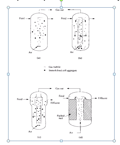 Figure 6
. Bubble column and air lift reactors: (a) bubble column; (b) air lift reactor; (c) air lift with particle separator; (d) packed bed air lift, , (adopted by ref. 5).
Fixed stationary particles or surface reactors
The most common reactor configuration used for immobilized cells is that of packed bed of particles. The advantages of packed beds include simplicity of operation and reasonable high mass transfer rates. Problems in the operation of packed beds include obstruction by uncontrolled cell growth and compression of the particles leading to excessive pressure drops. For these reasons simple packed bed reactors are mostly used for the case of non viable cells.
Packed bed reactors
Packed beds can either be run in the submerged mode (with or without aeration) or in the trickle flow mode as shown in Figure 7.
 Figure 7.
 Schematic presentation of packed bed reactors (a) packed bed; (b) packed bed with external aeration column,
A variety of packing is available for this purpose, both polymer, ceramic, glass and natural (wood or bark) in dumped and structured forms, porous or non-porous in a variety of shapes and sizes. Recently monoliths have become available similar to those in catalytic exhausts of cars. These give very high surfaces for cell immobilization and thin films with minimal mass transfer limitations can be formed. The flow velocities in the channels can be high to eliminate external mass transfer limitation in the adjacent liquid film as well. Simultaneously, plugging can be avoided, albeit at the cost of high pressure drop.
Fixed beds in anaerobic operation (e.g. digestion with methane production) can be run in recycle mode to avoid gas building up in the packing. With low gas production rates, recycling is not needed, and a gradient of concentration may be established. In contrast to fluidised beds, no hydrodynamic requirements have to be fulfilled, except for even distribution of the flow over the entire cross-section. It should be remarked that as with gas absorbers or other packed bed operations any maldistribution of the liquid flow will result in poor performance (e.g. channelling). Plugging of the beds may occur as rapidly as every 1 or 2 days and this makes periodic cleaning necessary. Injecting air and using a higher liquid flow rate for a short period will normally dislodge excess biomass. This sudden burst of biomass in the effluent has to be separated (e.g. by sedimentation) and collected for further treatment.
Biosorption technology has been implemented traditionally in packed bed columns similar to the ion exchange systems. However, biosorption as metal ion removal mechanism, can be implemented in any appropriate reactor configuration.
Trickle Bed Reactors
Trickle beds (Figure 8) with countercurrent flow of gas and liquid are used on a large scale for vinegar production, as biofilters for gas clean-up and deodorisation, for water purification and for ore leaching. Trickle beds can be operated with or without recycling, but recycling allows higher loading and gives better flow distribution, which is even more critical than in submerged packed bed operation. Cleaning is again possible by flooding the filter and proceeding as with submerged fixed bed reactors. In the case of gas purification, the gas is cleaned in a single passage and the liquid is there both as an absorption fluid and as nutrient supply to the biomass on the packing (usually wood shavings or bark). Excess biomass is settled out of this stream and no other cleaning is needed.

Figure 8. Trickle bed reactors (a) trickle bed or biofilter; (b) waste water trickling filter
Moving surface reactors
In this reactor category, mass transport is enhanced by the movement of large surfaces within the reactor. A typical example of such reactors is Rotating Biological Contactors (RBC) and Moving Bed Sand Filters
Rotating Biological Contactors (RBC)
Rotating biological contactor contain a number of rotating discs on a shaft submerged in a tank partially or completely filled with liquid, (Figure 9). Biofilm grows in immobilized form on the surface of a large number of closely spaced discs or inside corrugated packing units that slowly rotate in a trough, partially immersed in liquid and partially in the air space above the reactor (Figure 9). During the passage in the air or gas space, the liquid drains from the plates or packing and oxygen can diffuse in the remaining thin film of liquid and ultimately reach the biomass itself, and simultaneously CO2 can escape. Then the surface rotates further back in the liquid entraining air in the liquid, effectively aerating the fluid as well. The rotation and resulting mixing lead to very efficient mass transfer of nutrients and products to and from the film. As the film grows thicker, will eventually inactivate and detach. The released biomass can be recovered from the bottom of the reactor where it accumulates. The discs or packing are rotated at only a few rpm, and this limits the shear but is enough to control the film thickness to below 1-2 mm. As obviously some axial mixing will occur in this reactor configuration, the reactor can be compartmented with baffles to separate groups of discs, yielding a cascade of stirred tanks. This allows for complete conversion and still high concentrations and high conversion rates in a large part of the equipment. This is especially useful for dilute streams that are well described by a first-order conversion rate and hence benefit from a plug flow pattern, such as in dilute waste stream treatment. It should also be remarked that a fully submerged operation is possible in the case of anaerobic operation. Some of the advantages of good mass transfer are then lost but gas disengagement is easy and plug flow can be approached.
RBCs have been applied in denitrification of wastewater.
 Figure 9.
 Schematic view of an RBC reactor.
Moving Bed Sand Filter
In a moving bed sand filter developed by ASTRASAND, (Figure 10), wastewater is dosed 'in-line' with a polyelectrolyte before being fed into the filter at (1) and then into the filter bed at (4) through the supply manifold, (2) and distributors, (3). The water is filtered as it passes upwards through the sand bed with the treated 'filtrate' discharged in the upper part of the unit, at (5). The sand bed is continuously moving downwards as the water rises. The 'dirty' sand (6) is abstracted from the bed and raised to the upper part of the filter, after which it is released back on top of the sand bed (7). The sand circulation is based on the airlift principle forcing a mixture of dirty sand and water upwards through a central pipeline (8). The intensive scouring separates the impurities from the sand particles. At the top of the pipeline the air is released, the dirty (wash) water discharged (9) and the sand settles in the washer (10). As the sand passes through the washer labyrinth the particles are finally rinsed by a small amount of clean filtrate flowing through the washer counter-currently. The filtrate flow is generated by a difference in discharge level between the filtrate (11) and the washwater (10). The filter performance can be optimised by varying the airlift to control the sand circulation speed.
 Figure 10.
 A schematic presentation of a moving bed sand filter, (Adopted by Kramer, J.P., Wouters, J.W., Noordink, M., Moving bed biofiltration for dynamic denitrification of 3,600 m3/h sewage effluent published at the World Filtration Congress, Brighton, UK, 1999).
Types of Anaerobic Reactors
There are five principal process variants which are proper in anaerobic wastewater treatment. These are as follows:
- Anaerobic Filter. The anaerobic filter is similar to a trickling filter in that a biofilm is generated on media. The bed is fully submerged and can be operated either upflow or downflow. For very high strength wastewaters, a recycle can be employed.
- Anaerobic Contact. This process can be considered as an anaerobic activated sludge because sludge is recycled from a clarifier or separator to the reactor. Since the material leaving the reactor is a gas-liquid-solid mixture, a vacuum degasifier is required to separate the gas and avoid floating sludge in the clarifier.
- Fluidized Bed. This reactor consists of a sand bed on which the biomass is grown. Since the sand particles are small, a very large biomass can be developed in a small volume of reactor. In order to fluidize the bed, a high recycle is required.
- Upflow Anaerobic Sludge Blanket (UASB). Under proper conditions anaerobic sludge will develop as high density granules. These will form a sludge blanket in the reactor. The wastewater is passed upward through the blanket. Because of its density, a high concentration of biomass can be developed in the blanket.
Anaerobic processes usually operate at a temperature of 35 C. In order to maintain this temperature, the methane gas generated in the process is used to heat the reactor. Anaerobic reactor types are show in the following figure.
Spectacular Mountain
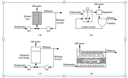
Figure 11. Schematic diagrams of anaerobic wastewater treatment processes: (a) anaerobic filter reactor; (b) anaerobic contact reactor; (c) fluidized-bed reactor; (d) upflow anaerobic sludge blanket (UASB).
Selection of Bioreactors
Selection of a reactor, is often determined by economics, reliability, or availability of a proven system. The selection of an appropriate reactor type or configuration for an immobilized cell system must be based on critical issues such as supply and removal of gases and solutes in the liquid phase and removal of excess biomass formed. The cell aggregates can only be fully active if the external supply or removal rates match the internal transport, utilization and production rates. The high cell densities in the reactors put higher demands on nutrient supply and transport rates and this is especially problematic for the sparingly soluble oxygen, requiring high circulation rates which may be in conflict with other design criteria.
Correct selection of the reactor type can alleviate many of the aforementioned problems, but many reactor types can be modified to adapt to the specific demands imposed by the waste water organic content, the selected microorganisms or specific operational conditions. Sterility and stringent cleaning procedures, usually is not required in the case of waste water treatment plants. Cost is obviously the main issue as no added value products are produced in a waste water treatment plant.
One of the major motivations in using immobilized systems is the possibility to run in continuous operation. In this fashion, the unproductive time in batch and fed-batch, associated to filling, emptying and start-up of the reactor is eliminated. However, in many cases (e.g. biofilms, or porous preformed supports) the biomass needs to be generated from the mixed population present in the non-sterile feed such as in the waste water treatment units. This may take up a significant amount of time (up to several weeks) and the associated cost can only be justified if the production time will be much longer.
Applications - Case studies
ASTRASAND(r) is a new and improved continuous sandfilter, developed for physical-chemical and/or biological treatment of different types of water, such as process, waste, surface, cooling and ground water. ASTRASAND(r) works as a continuous process, in which the filter bed is cleaned during the filtration operation, and as a result process interruptions are eliminated. ASTRASAND(r) is self-cleansing.
THIOTEQ(r) (formerly named THIOPAQ) A technology for producing biogenic H2S to remove metal ions by mining and metallurgical water streams.
SULFATEQ(r) A technology developed to remove sulphates and produce H2S, closely linked with the THIOTEQ(r) system.
BIOMETEQ(r) A technology embedded in an ASTRASAND filtration system based on a self-cleaning sand filter with bacteria that cause common heavy metals such as Iron, Copper, Nickel, Zinc, Lead, Cadmium and Mercury to precipitate as metal sulphides. Metal (loid)s like Selenium, Molybdenum, Chromium and Uranium are precipitated into elemental form (selenium) or as metal (hydr)oxides.