Alkylation
- In this lecture we present a brief overview of the alkylation process.
- In an alkylation process, olefins are reacted with isoparaffins to yield alkylate product.
- The basic purpose of alkylation is to enhance the octane number of the feed stock.
- For instance, octane number of butane alkylate is about 92–97. This is due to the formation of a hydrocarbon with side chain arrangement of carbon and hydrogen atoms.
Reaction Mechanism
There are three basic reaction steps to achieve alkylation.
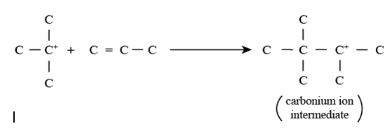
Step 1 involving Carbonium ion formation: In this reaction, alkene reacts with a proton (acid catalyst) to produce a proton substituted olefin. The proton substituted olefin reacts with isoparaffin to generate a reactive carbonium ion and alkane.
 Step 2
 involving carbonium ion intermediate formation: In this reaction, the carbonium ion formed in step 1 reacts with the olefin to produce an intermediate carbonium ion.
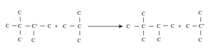
 Step 3
 involving regeneration of carbonium ion: In this reaction, the intermediate carbonium ion reacts with the isoparaffin to produce alkylate product and carbonium ion. Thus carbonium ion is again regenerated to take part in step 2 reactions along with other additional unreacted olefin molecules.
Reaction conditions
- To avoid olefin polymerization, high isobutane to olefin ratios are used.
- Typical isobutene to olefin ratios are 5:1 to 15:1.
- Acid catalysts are used. Primarily sulphuric acid (H2SO4) or HF are used.
- Depending on the acid catalysts choosed the process complexity varies. We present both process technologies to indicate the pertinent process complexity.
- Reaction operating temperature: 10–20 °C using H2SO4 and 25–40 °C using HF.
- Reaction temperature: 4.4 bar for H2SO4 and 7.8 bar for HF.
- When H2SO4 is used refrigeration is used.
- When HF is used, refrigeration is not used.
Sulfuric acid based alkylation process technology (Fig. 1)
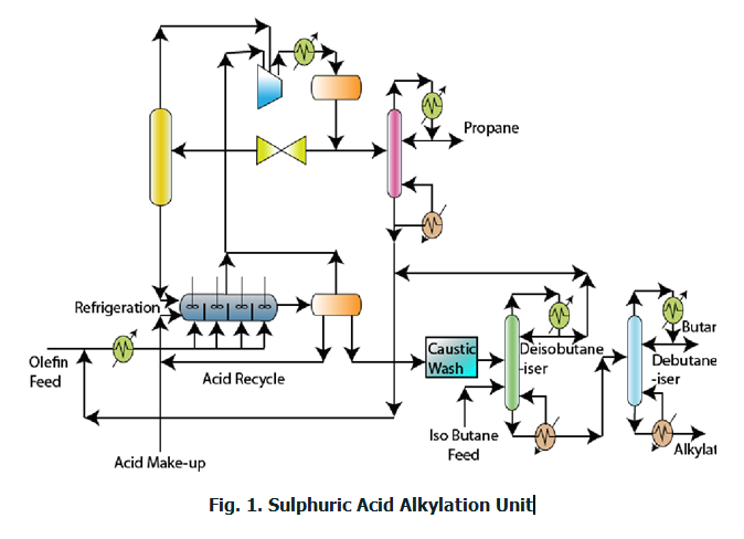 Caustic wash:
 The feed mixture (olefin + C4 compounds) are first subjected to caustic wash. During caustic wash, sulphur compounds are removed and spent caustic is recycled back to the caustic wash. Fresh caustic solution is added to take care of the loss.
Refrigeration: The olefin feed enters a refrigeration unit to reduce the feedstock temperature.
Alkylation reactor: The reactor is arranged as a series of CSTRs with acid fed in the first CSTR and feed supplied to different CSTRs. This arrangement is for maximizing the conversion.
- In the alkylation reactor it is important to note that the olefin is the limiting reactant and isoparaffin is the excess reactant.
- The alkylator unit therefore will have two phases in due course of reaction namely the olefin + isoparaffin mixture which will be lighter and the alkylate stream which will be heavier and will be appearing as a bottom fraction if allowed to settle.
- Since excess isoparaffin is used, the isoparaffin can be easily allowed as a bypass stream.
- Eventually, the alkylate product from the last reactor will be taken out as a heavy stream.
- Thus, the alkylation reactor produces two streams. These are (a) isoparaffin rich organic phase and (b) alkylate rich phase along with acid and isobutane phases.
- These streams should be subjected to further purification.
Phase separator: It so happens that the acid enters the organic rich stream and will be subjected to phase separation by settling. Similarly, the olefin/isoparaffin mixture will be also separated by gravity settling. Thus the phase separator produces three streams namely (a) olefin + isoparaffin rich phase (b) acid rich stream (c) alkylate rich stream.
Olefin + Paraffin processing: The olefin + paraffin stream is first subjected to compression followed by cooling. When this stream is subjected to throttling and phase separation, then the olefin + paraffin rich stream will be generated. The propane rich stream from this stream is generated as another stream in the phase separator.
Propane defractionator: The propane rich stream after cooling is fed to a fractionator where propane is separated from the olefin+isoparaffin mixture. The olefin+isoparaffin mixture is sent back to mix with the olefin feed.
Caustic wash for alkylate rich stream: The caustic wash operation ensures to completely eliminate acid concentration from the alkylate.
Alkylate fractionation: The alkylate is fed to a distillation column that is supplied with isobutane feed and alkylate feeds to produce isobutane as a top product and alkylate + butane mixture as a bottom product.
Debutanizer: The debutanizer separates butane and alkylate using the concept of distillation.
HF process technology (Fig. 2)

- The process is similar to the sulphuric acid plant. However, additional safety issues make the process complex.
- The feed is first subjected to drying followed by pre-cooling.
- After pre-cooling the reaction mixture the reaction mixture is fed to a reactor.
- Unlike CSTRs in series here impeller reactors are used. The reactor consists of cooling tubes to absorb the heat generated.
- The reaction products enters a settler where oil and the HF are separated.
- Since there can be traces of HF in the oil rich phase and vice-versa additional processing is followed.
- The HF rerun column removes traces of oils from the bulk of the HF. Thus HF purified will be recycled back to the reactor. The bottom product thus generated in this unit is acid oils.
- A HF stripper is used to remove the HF in lower quantities from the alkylate product. Eventually, the HF stripper produces HF that is sent back to the reactor and the alkylate product.
- The alkylate product is sent to a deisobutanizer and depropanizer units. The final alkylate product is produced by using a deflourinator which is basically a caustic wash or adsorption unit. Finally n-butane + alkylate is produced as the bottom product.
Introduction
In this lecture, we present an overview of light end processing followed with gas processing and polymerization processes in the refinery.
- Gas fraction is produced from various units. Some of them are,
- Crude distillation unit
- Catalytic cracking unit
- Catalytic reforming unit
- Hydrocracking unit
- Coking unit
The light end streams are classified as,
- Streams rich in Butane: Sold as calor gas or LPG. Used internally for blending and alkylation units
(isobutane only).
- Streams rich in Propane.
- Light ends rich in olefins.
We have already studied alkylation and isomerisation as important gas processing operations. Now we will study the additional units namely gas processing and polymerization units.
Gas processing technology (Fig. 3)
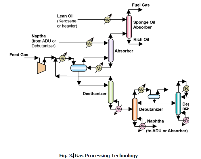
The objective of gas processing is to produce ethane and methane.
The produced ethane and methane is to serve later for fuel gas or hydrogen production.
The gas processing section consists mainly of two different sections.
Absorption using Naphtha and kerosene:
- First, collected gases are compressed to be fed to an absorption.
- The purpose of naphtha is to absorb heavier hydrocarbons in the gas fraction. These are C3s and C4s in the feed stream. To carry out absorption, first the gases are cooled and fed to a phase separator to facilitate early separation of lighter and heavier fractions.
- From the phase separator two streams emanate namely a gas stream and a liquid stream.
- The gas stream is fed to an absorber unit where naphtha is used as a solvent to absorb the left heavier hydrocarbons in the gas.
- The naphtha rich with hydrocarbons is fed to the phase separator so as to stabilize the naphtha stream.
- The gas from the absorber is fed to a second absorber where lean oil (such as kerosene) is used as a solvent to absorb any heavier hydrocarbons other than the methane and hydrogen. Eventually, fuel gas is produced as the gas product from this absorption. The other product from the absorber is the rich oil stream.
Naphtha rich stream processing:
- The liquid product from the phase separator is fed to a deethanizer which generates ethane rich stream as the top product. This stream is recycled back to the gas processing unit i.e., mixing with the feed and subjected to cooling followed by phase separator.
- The bottom product from deethanizer is naphtha rich stream with butanes and propanes.
- This stream is subjected to fractionation using debutanizer, depropanizer and deisobutanizer to obtain propane, isobutane and naphtha. The stabilized naphtha can be used for absorption purposes.
Olefin Polymerization
- Olefin polymerization to yield polymer gasoline is primarily carried out to obtain polymers with good octane numbers.
- The octane number of the polymer gasoline product is not greater than the octane number of the products produced from reforming and alkylation. Instead, comparatively poor quality product is obtained. But for the sake of enhancing octane number polymerization is carried out.
- On the other hand, polymer gasoline has more vapour pressure than the corresponding alkylation products. Therefore, in both ways, polymer gasoline product quality is lower than that obtained from the alkylation unit.
- Typical feedstocks for polymerization process are C3 and C4 olefins that are obtained from catalytic cracking.
- The end product from polymerization reactor is a dimer or a trimer of the olefins.
Reaction mechanism & Operating conditions
Reaction mechanism comprises of four basic steps,
Carbonium ion formation (Step 1): Here, olefin reacts with acid catalyst to yield carbonium ion.
Additon reaction (Step 2): Carbonium ion reacts with olefin to generate intermediate carbonium ion.
Regeneration (Step 3): The intermediate carbonium ion converts to the dimer and generates back the proton on the catalyst surface.
Isomerization (Step 4): Straight chain proton substituted olefins convert to isomeric carbonium ions.
Catalysts used: Acid catalysts (H
2SO
4 ) are used.
Temperature: 150–220 oC are used. Too high temperatures give tar deposits.
Pressure: 25–100 atms.
Olefin polymerization process technology (Fig. 4)

•
Caustic wash: C3–C4 olefin feed subjected to caustic wash to remove H
2S and other sulphur compounds (such as mercaptans). These tend to poison the catalyst.
Water scrubbing: Eventually water scrubbing is carried out to remove dissolved impurities and generate waste water.
Polymerization reactor: The reaction mixture is heated, compressed and fed to a polymerization reactor. The reactor design is a shell and tube type design where catalyst is placed in the tube for the reaction to take place and cooling water is circulated in the shell side to control the temperature increase due to the exothermic reaction.
Fractionation: Subsequently, the reactor product is fed to a depropanizer and debutanizer to produce propanes, butanes and polymer gasoline. The polymeric product is further stabilization using hydrogenation stabilizer which converts any freely available double bonds to single bonds. The end product is polymer gasoline.